
American Alloy Flange Technical Data Chart
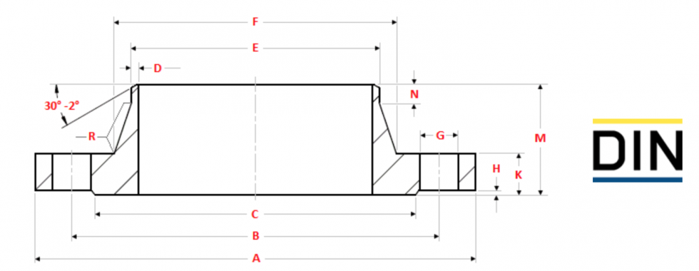
Diameters & Drilling of DIN Flanges ( mm )
| DN | A | B | C | D | E | F | G | H | K | M | N | R |
| 10 | 90 | 60 | 40 | 2 | 17.2 | 28 | 14 | 2 | 16 | 35 | 6 | 4 |
| 15 | 95 | 65 | 45 | 2 | 21.3 | 32 | 14 | 2 | 16 | 38 | 6 | 4 |
| 20 | 105 | 75 | 58 | 2.3 | 26.9 | 40 | 14 | 2 | 18 | 40 | 6 | 4 |
| 25 | 115 | 85 | 68 | 2.6 | 33.7 | 46 | 14 | 2 | 18 | 40 | 6 | 4 |
| 32 | 140 | 100 | 78 | 2.6 | 42.4 | 56 | 18 | 2 | 18 | 42 | 6 | 6 |
| 40 | 150 | 110 | 88 | 2.6 | 48.3 | 64 | 18 | 3 | 18 | 45 | 7 | 6 |
| 50 | 165 | 125 | 102 | 2.9 | 60.3 | 74 | 18 | 3 | 18 | 45 | 8 | 6 |
| 65 | 185 | 145 | 122 | 2.9 | 76.1 | 92 | 18 | 3 | 18 | 45 | 10 | 6 |
| 80 | 200 | 160 | 138 | 3.2 | 88.9 | 105 | 18 | 3 | 20 | 50 | 10 | 6 |
| 100 | 220 | 180 | 158 | 3.6 | 114.3 | 131 | 18 | 3 | 20 | 52 | 12 | 8 |
| 125 | 250 | 210 | 188 | 4 | 139.7 | 156 | 18 | 3 | 22 | 55 | 12 | 8 |
| 150 | 285 | 240 | 212 | 4.5 | 168.3 | 184 | 22 | 3 | 22 | 55 | 12 | 10 |
| 200 | 340 | 295 | 268 | 6.3 | 219.1 | 235 | 22 | 3 | 24 | 62 | 16 | 10 |
| 250 | 405 | 355 | 320 | 6.3 | 273 | 292 | 26 | 3 | 26 | 70 | 16 | 12 |
| 300 | 460 | 410 | 378 | 7.1 | 323.9 | 344 | 26 | 4 | 28 | 78 | 16 | 12 |
| 350 | 520 | 470 | 438 | 8 | 355.6 | 390 | 26 | 4 | 30 | 82 | 16 | 12 |
| 400 | 580 | 525 | 490 | 8 | 406.4 | 445 | 30 | 4 | 32 | 85 | 16 | 12 |
| 450 | 640 | 585 | 550 | 8 | 457 | 490 | 30 | 4 | 34 | 83 | 16 | 12 |
| 500 | 715 | 650 | 610 | 8 | 508 | 548 | 33 | 4 | 36 | 84 | 16 | 12 |
| 600 | 840 | 770 | 725 | 10 | 610 | 670 | 36 | 5 | 40 | 88 | 18 | 12 |
| 700 | 910 | 840 | 795 | 10 | 711 | 755 | 36 | 5 | 40 | 104 | 18 | 12 |
| 800 | 1025 | 950 | 900 | 12.5 | 813 | 855 | 39 | 5 | 62 | 108 | 20 | 12 |
| 900 | 1125 | 1050 | 1000 | 12.5 | 914 | 955 | 39 | 5 | 64 | 118 | 20 | 12 |
| 1000 | 1255 | 1170 | 1115 | 12.5 | 1016 | 1058 | 42 | 5 | 68 | 137 | 22 | 16 |
| 1200 | 1485 | 1390 | 1330 | 14.2 | 1219 | 1262 | 48 | 5 | 78 | 160 | 30 | 16 |
| 1400 | 1685 | 1590 | 1530 | 16 | 1422 | 1465 | 48 | 5 | 84 | 177 | 30 | 16 |
| 1600 | 1930 | 1820 | 1750 | 17.5 | 1626 | 1668 | 56 | 5 | 102 | 204 | 35 | 16 |
| 1800 | 2130 | 2020 | 1950 | 20 | 1829 | 1870 | 56 | 5 | 110 | 218 | 35 | 16 |
| 2000 | 2345 | 2230 | 2150 | 22 | 2032 | 2072 | 62 | 5 | 124 | 238 | 40 | 16 |
| DN | A | B | C | D | E | F | G | H | K | M | N | R |
| DN | No of bolts |
Dia of Hex Bolts |
Length of Hex Bolts |
Dia of Stud Bolts |
Length of Stud Bolts |
| 10 | 4 | M12 | 50 | 1/2″ | 65 |
| 15 | 4 | M12 | 50 | 1/2″ | 65 |
| 20 | 4 | M12 | 55 | 1/2″ | 70 |
| 25 | 4 | M12 | 55 | 1/2″ | 70 |
| 32 | 4 | M16 | 60 | 5/8″ | 80 |
| 40 | 4 | M16 | 60 | 5/8″ | 80 |
| 50 | 4 | M16 | 60 | 5/8″ | 80 |
| 65 | 8 | M16 | 60 | 5/8″ | 80 |
| 80 | 8 | M16 | 65 | 5/8″ | 80 |
| 100 | 8 | M16 | 65 | 5/8″ | 80 |
| 125 | 8 | M16 | 65 | 5/8″ | 85 |
| 150 | 8 | M20 | 70 | 3/4″ | 95 |
| 200 | 12 | M20 | 75 | 3/4″ | 95 |
| 250 | 12 | M24 | 85 | 7/8″ | 110 |
| 300 | 12 | M24 | 90 | 7/8″ | 110 |
| 350 | 16 | M24 | 90 | 7/8″ | 115 |
| 400 | 16 | M27 | 100 | 1″ | 130 |
| 450 | 20 | M27 | 105 | 1″ | 130 |
| 500 | 20 | M30 | 110 | 1.1/8″ | 145 |
| 600 | 20 | M33 | 120 | 1.1/4″ | 160 |
| 700 | 24 | M33 | 120 | 1.1/4″ | 160 |
| 800 | 24 | M36 | 170 | 1.3/8″ | 210 |
| 900 | 28 | M36 | 175 | 1.3/8″ | 215 |
| 1000 | 28 | M39 | 185 | 1.1/2″ | 230 |
| 1200 | 32 | M45 | 210 | 1.3/4″ | 265 |
| 1400 | 36 | M45 | 225 | 1.3/4″ | 275 |
| 1600 | 40 | M52 | 270 | 2″ | 325 |
| 1800 | 44 | M52 | 285 | 2″ | 345 |
| 2000 | 48 | M56 | 315 | 2.1/4″ | 385 |
| DN | No of bolts |
Dia of Hex Bolts |
Length of Hex Bolts |
Dia of Stud Bolts |
Length of Stud Bolts |
Indications:
|
|
 |
General notes:
- Dimensions are in millimeters unless otherwise indicated.
- Butt-weld ends (must be specified when ordering) acc. to DIN 3239-1-R6 edge form 22 to DIN 2559 (DIN EN ISO 9692)
Special notes:
- Hex bolt lengths and diameters & lengths of Stud Bolts are calculated by the author of this website.
- All lengths are calculated without washers, spring washers etc. and free threads (equals 1/3 time bolt diameter)
- All lengths are calculated with a gasket thickness of 3 mm.
- The dimensions of the bolts are calculated for the type 11 weld neck flange. Other types of flanges can be have
different bolt hole diameters and thicknesses, so that the bolts even can have different dimensions.

Limitation of Liability and Disclaimer of Warranty: In no event will South Coast Industrial Metals or any of its affiliates be liable for any damages arising from the use of the information included in this document or that it is suitable for the ‘applications’ noted. We believe the information and data provided to be accurate to the best of our knowledge but, all data is considered typical values only. It is intended for reference and general information and not recommended for specification, design or engineering purposes. South Coast Industrial Metals, Inc. assumes no implied or express warranty in regard to the creation or accuracy of the data provided in this document.